
Your Source for Trays!

Why Choose CCS Busbar for Battery Applications?

Electric vehicle growth is increasing pressure on battery makers to deliver compact, reliable power systems. The International Energy Agency’s Global EV Outlook 2024 reports that nearly 14 million electric cars were sold in 2023, representing about 18% of new car sales worldwide. IEA Executive Director Fatih Birol called this growth “a very encouraging sign.” More vehicles mean more attention to the connections inside each battery pack.

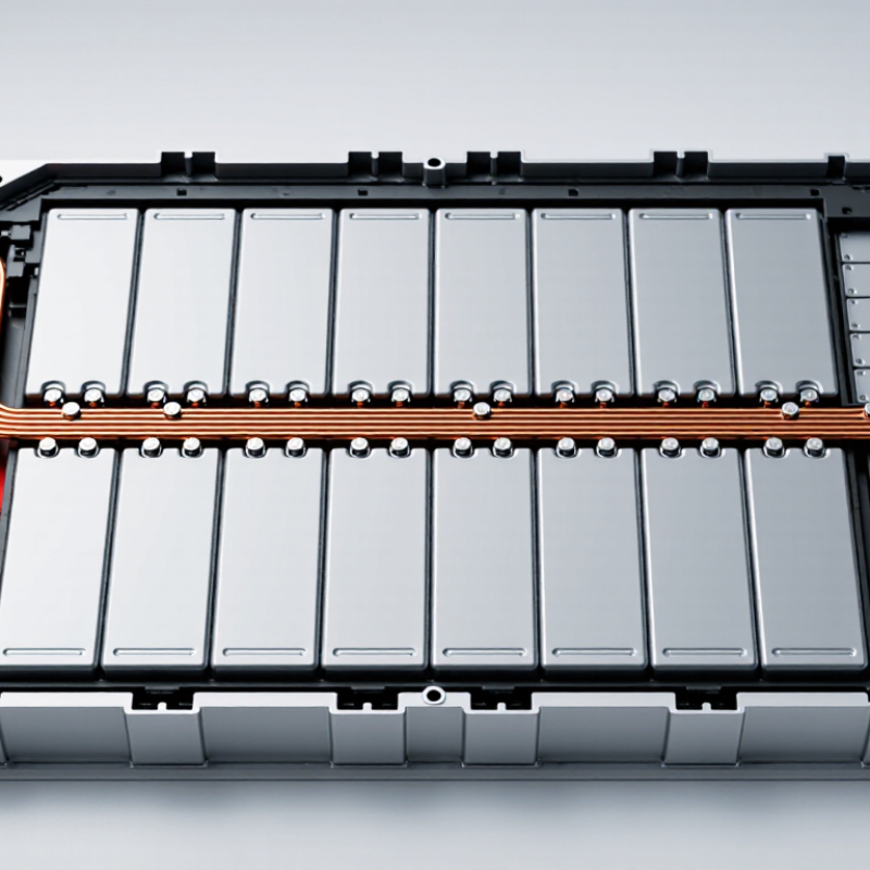
A CCS Busbar combines electrical interconnection with cell monitoring and sensing functions. In a battery module, it can link cells while helping collect voltage and temperature signals. That integrated layout may reduce separate wiring, simplify assembly, and create a tidier pack. Picture a row of cells joined by a shaped conductor, with sensing points routed alongside it. Fewer loose connections can make manufacturing easier to manage. Not magic, though.

The right design depends on cell format, current demand, insulation, thermal conditions, and production requirements. Engineers still need to assess resistance, heat rise, mechanical fit, and sensing accuracy in the finished pack. A busbar that works well in one module may not suit another. That detail is easy to overlook.

For battery designers, the case for a CCS Busbar is practical: integration can save space and support consistent assembly. But claimed benefits should be checked against real pack testing, not just a component datasheet. That is where careful engineering matters most.
Why Choose CCS Busbar for Battery Applications?

What a CCS Busbar Is and How It Is Constructed

A CCS busbar is part of a cell contacting system: the electrical links and sensing connections that join battery cells into monitored groups. It is not a single bare strip. Typically, copper or aluminum conductors sit in a molded insulating carrier, with voltage-sensing leads routed alongside them. The carrier keeps parts aligned and helps prevent accidental contact. Small details matter.

During assembly, busbar ends are joined to cell terminals, often by laser or ultrasonic welding. The chosen metal, thickness, joint geometry, and insulation must suit the current, heat, vibration, and available space. A thin copper link can carry substantial current, but poor joints create resistance and localized heating. Manufacturers therefore inspect weld consistency and electrical continuity. A neat appearance is not proof of a sound connection.

The International Energy Agency’s Global EV Outlook 2024 reported that EV battery demand reached about 750 GWh in 2023, roughly 40% above 2022. That scale makes repeatable cell-contact construction increasingly important, but it does not make every CCS design interchangeable. Pack layout, cooling, and service requirements still shape the busbar. And tolerance stack-up can be stubborn: a carrier that fits the drawing may not sit perfectly against real cells. Build trials and measurement remain essential.

How CCS Busbars Connect Battery Cells and Monitor Temperature

A cell contact system, or CCS busbar, links battery cells into a planned electrical path. Thin conductive strips connect cell terminals, often through welded joints designed for the pack’s current and vibration levels. The layout also helps keep connections compact. Every millimeter matters in a crowded module.

Temperature sensing adds another layer. Small sensors, such as thermistors, sit near selected cells or busbar areas. Fine signal wires carry readings to the battery management system, which can flag unusual heating. Sensor placement matters: a probe too far from a hot spot may respond late. Readings also depend on contact, airflow, and measurement intervals. A tidy layout helps, but it cannot fix poor calibration.

Tips: Check that sensor leads are secured away from sharp edges and high-current paths. During inspection, look for loose joints, damaged insulation, or uneven discoloration. These signs need investigation, not guesswork. CCS designs vary, so confirm spacing, materials, and sensor locations against the pack’s specifications. Even a well-designed system has limits.

Why Choose CCS Busbar for Battery Applications? — How CCS Busbars Connect Battery Cells and Monitor Temperature

Design Dimension Typical Configuration or Data Battery-Application Benefit
Cell interconnection Conductive busbars connect cell terminals in series, parallel, or series-parallel arrangements. Creates electrical paths between cells and helps organize connections within a module or pack.
Conductor material Copper and aluminum are commonly used. At about 20°C, their electrical conductivities are approximately 58 MS/m and 35 MS/m, respectively; actual values depend on material grade and condition. Copper offers higher conductivity per cross-sectional area, while aluminum can reduce conductor mass. Material choice also affects joining, corrosion control, and cost.
Current-carrying capacity No single current rating applies to all CCS busbars. Capacity is determined by conductor dimensions, joint resistance, cooling, allowable temperature rise, and pack layout. Sizing for the application helps manage resistive heating and voltage drop under expected operating and fault conditions.
Temperature sensing An integrated CCS may route sensor connections to cell or busbar areas. NTC thermistors are commonly used; a 10 kΩ nominal resistance at 25°C is one available specification, not a universal standard. Sensor signals can be read by the battery-management system to support temperature monitoring and protective control strategies.
Signal routing Flexible printed circuits or other insulated wiring can carry sensing and monitoring signals alongside the busbar assembly. Combines cell interconnection and signal routing in a structured assembly, potentially reducing separate wiring and assembly steps.
Electrical insulation Insulating carriers, films, or covers separate conductive paths and help protect against unintended contact. Required clearances and insulation ratings depend on pack voltage and applicable standards. Supports electrical isolation and helps reduce the risk of short circuits when designed for the specific voltage, environment, and assembly.
Joining and contact resistance Welding, bolting, or other qualified joining methods may be used, depending on cell terminals and conductor materials. Joint resistance and mechanical integrity require validation. Reliable joints help limit localized heating and maintain electrical continuity through vibration and service conditions.
Thermal design Temperature rise depends on current, conductor resistance, joint quality, heat transfer, and ambient conditions. Sensor placement should reflect the locations that need monitoring. Integrated monitoring can help identify abnormal heating, but it does not replace thermal testing or appropriate protection design.
Mechanical integration The assembly is designed around cell spacing, terminal positions, tolerances, expansion, vibration, and enclosure constraints. A layout matched to the cell arrangement can simplify installation and reduce the chance of assembly interference.
Validation Typical checks include dimensional inspection, continuity and resistance testing, insulation testing, thermal assessment, and mechanical evaluation. Testing confirms that the complete assembly meets its specified electrical, thermal, and mechanical requirements.

Note: Values and configurations shown are general engineering references. Final busbar dimensions, sensor selection, ratings, insulation, and validation requirements must be determined for the specific battery design.

Key Benefits of CCS Busbars in Battery Pack Design

Why Choose CCS Busbar for Battery Applications?

A CCS busbar can combine cell interconnects, voltage-sensing conductors, and an insulating carrier in one compact assembly. This reduces loose wiring inside a battery pack and helps keep connections organized. During assembly, aligned contact points can make module integration more repeatable. Fewer separate parts may also reduce handling steps. Small details matter.

In a tightly packed module, a shaped busbar can follow the cell layout while leaving room for cooling paths and enclosure features. Integrated sensing routes make it easier to monitor individual cells, provided connections are correctly designed and tested. The carrier can help maintain spacing, but it does not replace suitable insulation or mechanical checks. Current capacity, material choice, joint resistance, and heat dissipation still need careful validation. Integration has trade-offs: a custom assembly may be harder to inspect or repair than separate components. That deserves attention early in the design.

Tips: Check clearances around terminals and cooling channels. Verify temperature rise under realistic loads. Review sensing continuity after vibration testing. Keep access for inspection; it is easy to overlook.

How CCS Busbars Support Safety and Manufacturing Efficiency

CCS (cell connection system) busbars combine conductive links, insulation, and sensing connections into a compact assembly. In battery packs, that integration can reduce loose wiring and repeated manual connections. Fewer separate parts can make assembly more consistent, though the result depends on precise placement and reliable joints. Small details matter. A shifted busbar or damaged insulating layer can create a weak point.

Safety comes from design and validation, not from the busbar alone. Enclosed conductors can reduce accidental contact, while controlled spacing helps manage electrical clearances. Temperature, vibration, and fault-current testing remain essential. The International Energy Agency’s Global EV Outlook 2024 reports that global battery manufacturing capacity reached about 2.5 TWh in 2023. At this scale, repeatable assembly and inspection are practical priorities. CCS layouts can support automated handling, but they also demand tight dimensional control; a missed tolerance still hurts.

Tips: Check joint resistance, insulation condition, and sensor placement during production. Validate the assembly under real thermal and vibration conditions. Keep a clear inspection record. Automation helps, but it does not catch every defect.

Factors to Consider When Selecting a CCS Busbar for Batteries

Selecting a cell-contact-system (CCS) busbar starts with the battery’s real operating profile, not a catalog current rating. Record continuous and peak current, voltage, temperature range, and expected cycling. The IEA’s Global EV Outlook 2024 reports that electric-car battery demand exceeded 750 GWh in 2023, up about 40% year over year. That scale makes repeatable connections and production tolerances important. Fit matters. Check cell spacing, busbar thickness, and joint alignment against actual pack samples, not drawings alone.

Material and insulation choices affect heat, weight, corrosion resistance, and cost. Copper offers high conductivity; aluminum can reduce mass but needs careful joint design. Check temperature rise under peak load, and confirm insulation, creepage, and clearance suit the pack’s voltage and environment. The U.S. Department of Energy estimated 2023 light-duty EV battery-pack costs at about $139 per kWh. That figure is not a busbar price target, but it highlights the pressure to balance reliability with material and assembly costs. Test vibration, thermal cycling, and connection resistance. A tidy prototype can still hide weak joints. Review service access and manufacturing variation before freezing the design.