
585.204.6770
sale@sanblueplastics.com
Your Source for Trays!
Top 10 PCB Electroplating Rectifier Suppliers Worldwide
Choosing a Pcb Electroplating Rectifier Supplier is a practical decision, not just a search for the lowest quoted price. Rectifiers control the current and voltage used during plating, so their stability can affect coating consistency across a production run. Small details matter: the required current range, ripple level, cooling arrangement, control interface, and available service support. A unit that fits one factory may not suit another. It depends on the process.
This guide introduces ten suppliers serving the worldwide market. It considers product range, technical information, customization options, and support—not a single sales claim. Buyers should compare specifications against their own bath chemistry, line capacity, operating conditions, and maintenance plans. Ask how performance is measured. Check what the warranty covers. Confirm that replacement parts and technical help are realistically available in your region.
Numbers can look reassuring. Yet a polished brochure cannot show how a rectifier behaves on a busy shop floor. Supplier information may also change, and advertised capabilities deserve independent verification. That is worth remembering. The list is a starting point, not a final verdict. The right choice depends on documented requirements, careful conversations with suppliers, and, where possible, a production trial. Even experienced buyers can miss a detail. A comparison can narrow the field, but it cannot replace sound engineering judgment.
What PCB Electroplating Rectifiers Are and How They Work
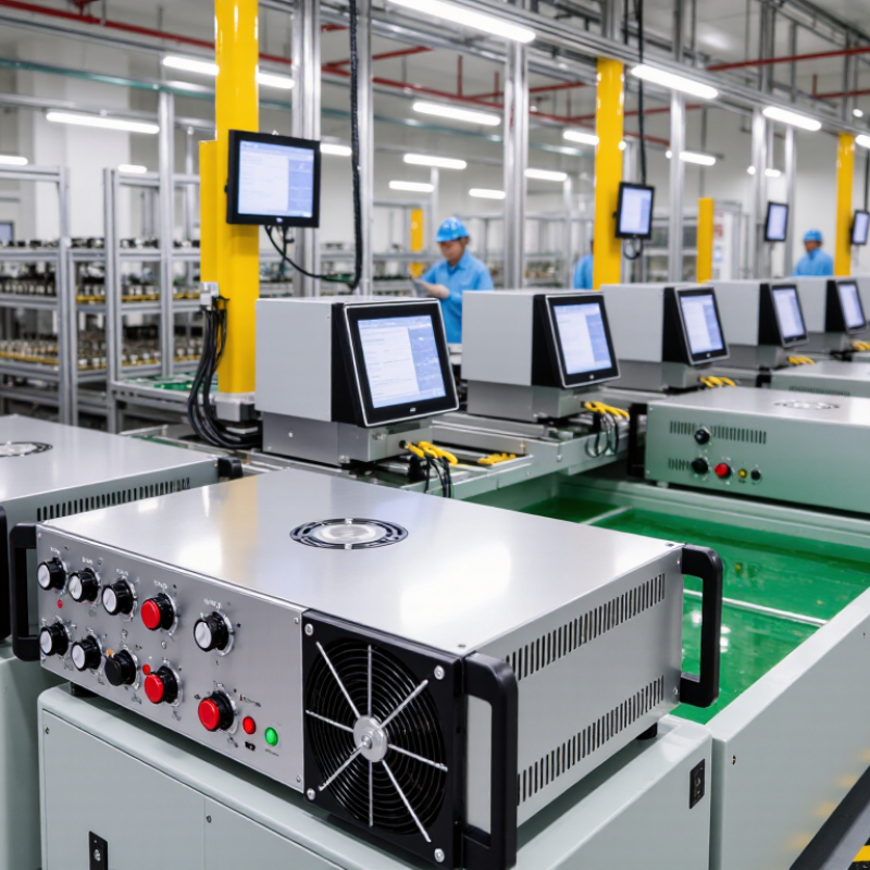
A PCB electroplating rectifier converts alternating current into controlled direct current. In a plating line, it drives copper ions from the electrolyte onto board surfaces and into drilled holes. This builds conductive layers and helps connect circuit layers. The rectifier controls current, voltage, and sometimes pulse timing; stable output supports more even copper thickness across the panel. That matters.
Faraday’s law gives a useful process check: at 100% current efficiency, one ampere-hour deposits about 1.19 grams of copper. Actual deposition is lower when side reactions consume current. Prismark’s 2024 Global PCB Industry Report estimated 2023 worldwide PCB production value at roughly US$68 billion. That large production base depends on repeatable plating, though a rectifier alone cannot correct poor bath chemistry, uneven flow, or bad panel contact. The distinction is easy to overlook.
Tip: Match rectifier capacity to panel area and target current density. Check ripple, current stability, and connections under real load—not just the nameplate rating. Record copper thickness across several panel locations; one reading can hide uneven plating.
Top 10 PCB Electroplating Rectifier Suppliers Worldwide – What PCB Electroplating Rectifiers Are and How They Work
This non-ranked comparison summarizes ten common rectifier configurations and supplier capability areas used in PCB electroplating. It focuses on equipment functions and selection criteria rather than naming or ranking companies.
| No. | Rectifier Configuration or Capability | How It Works | Typical PCB Plating Use | Key Selection Considerations |
|---|---|---|---|---|
| 1 | Single-output DC rectifier | Converts AC input into controlled direct current, with adjustable output voltage and current. | General electroplating processes where a stable DC supply is required. | Rated current, voltage range, current regulation, cooling method, and compatibility with the plating line. |
| 2 | Switch-mode rectifier | Uses high-frequency power conversion to regulate the output; many designs use switching devices and electronic feedback. | PCB lines that need efficient, compact power equipment and responsive output control. | Output ripple, efficiency, power factor, electromagnetic compatibility, and serviceability. |
| 3 | Thyristor-controlled rectifier | Regulates output by controlling the firing angle of thyristors in the power-conversion circuit. | High-current plating applications and installations where robust industrial power equipment is used. | Control accuracy, ripple characteristics, input harmonics, cooling, and installation requirements. |
| 4 | Pulse-plating rectifier | Delivers current in controlled pulses, with adjustable pulse timing and, on some models, pulse-reverse operation. | Processes where pulse parameters are specified to influence deposit distribution or plating performance. | Peak and average current ratings, pulse frequency, duty cycle, rise and fall times, and waveform accuracy. |
| 5 | Pulse-reverse rectifier | Alternates forward plating current with brief reverse-current periods according to programmed settings. | PCB plating processes that use forward and reverse pulses as part of a qualified process recipe. | Reverse-current control, timing resolution, waveform repeatability, and recipe storage. |
| 6 | Multi-channel rectifier system | Provides separately controlled outputs through multiple channels or power modules. | Lines with multiple plating zones or loads that require independent electrical control. | Channel isolation, independent setpoints, load balancing, monitoring, and system expandability. |
| 7 | Remote-control rectifier | Accepts setpoints and operating commands from an external controller or production system. | Automated plating lines that coordinate current settings with process stages. | Available interfaces, communication reliability, command limits, alarm handling, and integration testing. |
| 8 | Water-cooled rectifier | Transfers heat from power components to a cooling-water circuit. | Installations where heat load, equipment density, or the operating environment favors liquid cooling. | Cooling-water quality, flow and temperature requirements, leak protection, and maintenance access. |
| 9 | Air-cooled rectifier | Uses natural or forced airflow to remove heat from the power electronics. | Installations where the equipment rating and ambient conditions are suitable for air cooling. | Ventilation, ambient temperature, dust or corrosive exposure, fan maintenance, and required clearance. |
| 10 | Custom-engineered rectifier package | Combines a selected power stage, controls, enclosure, and cooling arrangement to meet a defined process specification. | Plating lines with particular output, automation, environmental, or integration requirements. | Documented operating limits, acceptance testing, safety provisions, spare parts, and after-sales support. |
An electroplating rectifier supplies controlled electrical current to the plating circuit. In a typical setup, the workpiece is connected as the cathode and the plating anode completes the circuit through the electrolyte. Actual current density, waveform, voltage, and plating time depend on the bath chemistry, workpiece area, equipment, and validated process specification.