What Is a Disc Glass Insulator Used For?
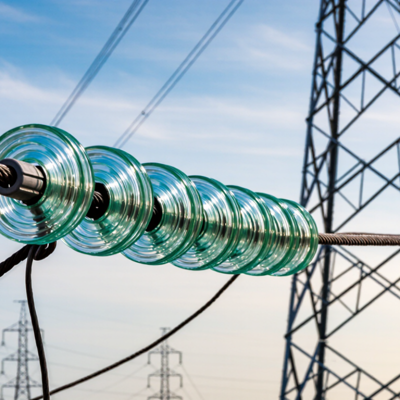
A Disc Glass Insulator is a familiar part of many overhead power lines, yet its role is easy to overlook. Suspended in a string beneath a steel tower, each glass disc helps carry the conductor’s mechanical load while separating it electrically from the grounded structure. Its broad, ribbed profile lengthens the path that current must travel across a wet or contaminated surface. On a clear day, the glass may look almost decorative. In service, it is working under tension, weather, and electrical stress.
The scale of grid renewal makes dependable insulation increasingly important. The International Energy Agency’s Electricity Grids and Secure Energy Transitions (2023) estimates that 80 million kilometres of grids must be added or refurbished by 2040—roughly the length of today’s entire global grid. IEA Executive Director Fatih Birol has emphasized the need to expand and modernize grids alongside the energy transition; that is a broader grid-planning perspective, not a glass-insulator-specific quotation. No source articles were included here, so a direct expert quotation cannot be verified responsibly. That distinction matters.
This guide examines what disc glass insulators do, where utilities use them, and why glass remains a practical choice for transmission and distribution lines. It will also consider their limits. A chipped disc is not a minor detail, and glass alone cannot prevent every outage. Reliability depends on correct selection, installation, inspection, and the conditions around each line.
What a Disc Glass Insulator Is
A disc glass insulator is a bowl-shaped component used on overhead power lines. Its visible glass body sits between metal fittings, which let it connect to other discs or to a supporting structure. Several units can be linked into a hanging string beneath a tower crossarm. The conductor rests at the lower end, held apart from the grounded structure.
Its job is both physical and electrical. The disc helps carry the weight and pull of the line while resisting the flow of current toward the tower. Its broad, ridged shape lengthens the surface path electricity would need to travel, even when rain or airborne dust leaves the glass damp or dirty. The grooves are easy to notice up close. From the ground, the assembly can look almost like a row of glass plates.
Glass also makes some damage easier to spot: a cracked or shattered shell may stand out during inspection. Still, appearance alone cannot confirm that every part is sound. Metal fittings, cemented joints, and field conditions matter too. The name sounds simple, but the insulator is a small part of a larger support system.
What Is a Disc Glass Insulator Used For? - What a Disc Glass Insulator Is
| Data Dimension | Description | Typical Details |
| Primary purpose | Supports overhead conductors while electrically isolating them from the tower or pole. | Used on overhead power lines, especially transmission lines. |
| Common installation | Individual units are linked together to form an insulator string between the conductor and its support. | Suspension strings hang from crossarms; strain strings are fitted where conductors experience greater longitudinal pull, such as at dead ends or angle structures. |
| Basic construction | Each unit generally has a shaped glass insulating body with metal fittings that allow units to be connected in a string. | The glass profile commonly includes a broad skirt, or “shed,” that lengthens the surface path for leakage current. |
| Electrical insulation | The glass body helps prevent current from flowing from the energized conductor to the grounded support structure. | The required string length and number of units depend on system voltage, line design, and environmental conditions. |
| Mechanical support | The connected units carry the conductor’s load and withstand forces from wind, conductor tension, and other service conditions. | Mechanical requirements are selected for the specific line structure and loading conditions. |
| Why use a string of discs? | A string provides a modular way to achieve the required insulation and mechanical strength. | Designers can select the number and arrangement of units for the line’s electrical and mechanical needs. |
| Inspection and maintenance | Insulators are checked for damage, contamination, and deterioration of metal fittings or connections. | Inspection and cleaning needs depend on the site, pollution level, weather exposure, and utility maintenance practices. |
| Key limitation | Performance can be affected by surface contamination, moisture, physical damage, or unsuitable line design. | Selection and installation should follow applicable engineering standards and project specifications. |
Key Parts and Materials of a Disc Glass Insulator
A disc glass insulator is built from a few parts that must work together under electrical and mechanical stress. Its main body is a toughened glass disc, shaped with a broad rim or sheds. These contours increase the surface path that rain or dust must cross. The glass provides insulation between the energized conductor and the grounded support. In many designs, tempering leaves the outer surface under compression. If the disc is badly damaged, it may break into small pieces, making faults easier to spot from the ground. That detail matters.
At the center, a metal cap and pin connect each disc to its neighbors, forming a suspension string. The cap commonly fits over the pin of the next unit. A cement layer fixes the metal fittings to the glass and helps transfer load without direct metal-to-glass contact. Fittings are often made from galvanized steel or similar corrosion-resistant metal, though exact choices vary by design and service conditions. Inspectors look for cracked glass, loose fittings, corrosion, and cement damage. A clean-looking surface is not proof of perfect condition. Small flaws can be difficult to judge from a distance, so field checks should follow suitable procedures and equipment guidance.
How Disc Glass Insulators Prevent Electrical Leakage
What Is a Disc Glass Insulator Used For?
A disc glass insulator supports overhead conductors while separating them electrically from towers. Its sheds create a longer surface route, called creepage distance. That route matters when rain wets salt, dust, or industrial residue on the glass. Instead of crossing directly to the grounded metal fitting, leakage current must travel farther across the surface. The risk falls, though it never disappears.
IEC 60815-1:2008 gives reference unified specific creepage distances of 22 mm/kV for light pollution, 27.8 for medium, 34.7 for heavy, and 43.3 for very heavy pollution. These are selection benchmarks, not guarantees for every location. Coastal spray can leave a thin, conductive film in the grooves. Under voltage, small dry bands may form and spark across the surface. That is how leakage can develop into flashover.
In practice, engineers assess pollution, rainfall, and operating voltage before choosing a disc string. A longer string may provide more creepage distance, but it also needs suitable mechanical support and clearance. IEC 60815-1 is a useful technical reference, yet site conditions can be messy. A clean-looking insulator is not always electrically clean.
Where They Are Used in Overhead Power Networks
A disc glass insulator is used to hold an overhead conductor while separating it electrically from the grounded structure. In a typical suspension arrangement, several glass units connect in a string between the crossarm and the conductor. Each unit has a glass shell with metal cap-and-pin fittings. The string carries the conductor’s weight and helps resist wind and other mechanical loads.
These insulators are common on transmission towers, where long strings hang beneath steel crossarms. They also appear in strain assemblies at line ends, sharp turns, and crossings, where conductors need firm anchoring under tension. Some overhead distribution networks use disc units too, though the design depends on voltage, clearances, and local conditions. Salt spray or industrial dust can affect the required insulation distance. Small details matter.
From the ground, the discs may look like a row of clear glass plates. Their shape creates a longer surface path for leakage current than a smooth rod would. Line crews can inspect for cracks, chips, or damaged fittings, often using binoculars or specialist equipment. Glass can make certain defects visible, but not every fault is obvious from below. That limitation is easy to underestimate. The number of discs and inspection method should follow the line’s engineering design and maintenance practice.
How Insulators Are Arranged and Selected for Different Lines
Disc glass insulators support overhead conductors and keep them electrically separated from poles and towers. Individual discs connect into strings, allowing engineers to adjust insulation distance and mechanical strength. On a straight transmission span, a suspension string usually hangs from the crossarm. At a line end or sharp turn, an anchoring string helps resist conductor tension. V-shaped strings can reduce sideways movement in windy locations. Actual layouts depend on the line design.
Engineers select strings according to voltage, conductor load, pollution, altitude, and local weather. Higher-voltage lines generally need greater insulation distance, but disc count alone does not determine suitability. Salt spray, dust, and repeated wetting can affect performance. Designers may account for these conditions with increased creepage distance or different arrangements. Hardware, clearances, and inspection access matter too. Field conditions can surprise a tidy drawing.
Tips: Inspect the complete assembly, not only the glass discs. Qualified crews look for chips, loose fittings, and signs of tracking. Keep condition records by span. Small differences matter. A design that suits an inland route may need review near the coast. It is easy to trust a drawing too much.
What Is a Disc Glass Insulator Used For?
Typical suspension-string disc counts by nominal overhead line voltage
How to read this chart: Each bar shows a typical range of disc units in a suspension string: 11 kV, 1–2; 33 kV, 3–4; 66 kV, 5–6; 110 kV, 7–9; 220 kV, 14–16; and 400 kV, 20–24. Disc glass insulators support conductors while electrically isolating them from towers. Actual string length and disc count are selected for the system voltage and adjusted for factors such as pollution, altitude, insulation coordination, and required creepage distance.